|
Central feeding system| RSS
|
|
central feeding system |
 |
central feeding system |
Manufacturing method of central feeding system |
source:Central feeding system Author:Central feeding system time:2020-10-22 10:34:00 |
|||
| The utility model relates to the technical field of central feeding equipment, in particular to a central feeding system. Background technique: Central feeding equipment is a large-scale feeding and processing system equipment commonly used in the field of plastic processing. The existing central feeding equipment often has the phenomenon that the pipeline is blocked by the rubber particles, especially the valve is installed in the position where it is easy to insert, difficult to unblock, and the maintenance is time-consuming and laborious. Therefore, it is necessary to provide a central feeding system, which is not easy to insert in series, and is easy to maintain and clear. Technical realization elements: The purpose of the utility model is to provide a central feeding system in view of the shortcomings of the prior art, which is not easy to insert and transport, and is easy to repair and dredge. In order to achieve the above-mentioned purpose, a central feeding system of the present invention includes a blow molding unit, a weighing meter, a storage barrel, a crusher and connecting pipes, as well as a cut-off valve, a cut-off valve, and a vacuum fretting material Cup, buffer bucket, secondary filter dust collector, fan, air pipeline system and material pipeline system; the air pipeline system includes a main ventilation pipe and multiple branch ventilation pipes; one end of the multiple branch ventilation pipes is cut off respectively The air valve is connected to the main vent pipe, the other end of the branch vent pipe is respectively connected to the vent of the vacuum micro-motion cup, and the separation of the secondary filter dust collector is respectively connected to the fan and the main vent pipe; the conveying pipe The system includes a main feed pipe and a plurality of branch feed pipes. One end of the multiple branch feed pipes is respectively connected to the main feed pipe through a cut-off valve, and the other end of the branch feed pipe is connected to the vacuum micro-motion feed cup. The feed port is connected, and the crusher is connected to the main feed pipe; there are multiple vacuum micro-movement cups, and the vacuum micro-movement cups are respectively installed in the buffer hopper, weighing meter, and storage bucket; buffer hopper It is installed in the blow molding unit; it also includes a cut-off valve provided with a base body, the base body is provided with a channel leading to the main feed pipe, a ventilation valve core is provided in the channel, a ventilation valve core is provided with a ventilation hole, and the base body is also provided with a driving valve A power unit that opens and closes the passageway. Further, it also includes a buffering barrel, and the separation of the buffering barrel is respectively connected with the grinder and the main feed pipe. Further, the cut-off valve is provided with two ventilation valve cores and two power devices, the two ventilation valve core transfer passages are arranged at intervals, the base body is provided with a mounting hole perpendicular to the passage, and the ventilation valve core slides relative to the mounting hole. Set up. Further, the embedding of the ventilation holes is 2mm-10mm. Further, the distance between the two ventilation valve cores is 1.5 to 3 times the diameter of the passage. Further, the base body is provided with a branch, the branch is connected to the passage, and the branch is arranged between the two ventilation valve cores; the branch is provided with a closed valve core, and the branch is connected with the branch feed pipe. Further, the power device is a linear electric cylinder, and the output shaft of the linear electric cylinder is connected to the ventilation valve core. The beneficial effects of the utility model: the two-stage filter dust remover of the utility model can effectively filter the dust in the air, avoiding dust and impurities, and the utility model uses the method of the main feed pipe and the multiple branch feed pipes to be connected in sections , Reduce dust accumulation, reduce the time for dust insertion; the ventilation hole of the air valve core of the present utility model can still ventilate when the material is cut off, and can use multiple ventilation methods to measure the pressure of the pipeline when the position is overhauled. A utility model of a central feeding system, which is not easy to insert a catheter, and is easy to maintain and clear. Description of the drawings Figure 1 is a schematic diagram of the connection structure of the utility model. Figure 2 is a schematic diagram of the blow molding unit structure of the utility model. Figure 3 is a schematic structural diagram of the shutoff valve of the present invention. Reference signs include: 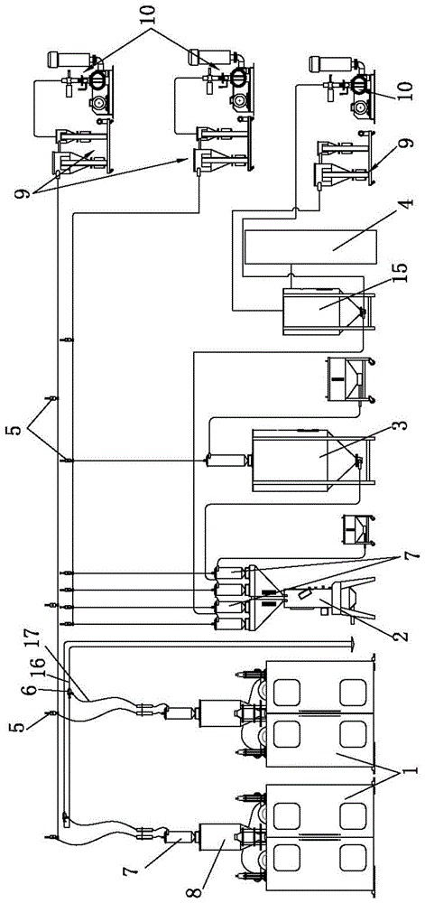 1—Blow molding unit 2—Weighing scale 3—Storage barrel 4—Crusher 5—Air cut valve 6—cutting valve 7—Vacuum fretting cup 8—Buffer bucket 9—Secondary filter dust collector 10—Fan 11—Access 12—Ventilation valve core 13—Power Plant 14—channel 15—Buffer barrel 16—Main feed pipe 17—Branch feed pipe. detailed description The following describes the utility model in detail with reference to the drawings. As shown, a central feeding system of the present utility model includes a blow molding unit 1, a weighing meter 2, a storage tank 3, a crusher 4 and connecting pipes, as well as a cutoff valve 5 and a cutoff valve 6. Vacuum fretting cup 7, buffer hopper 8, secondary filter dust collector 9, fan 10, air pipeline system and material pipeline system; The air pipeline system includes a main vent pipe and a plurality of branch vent pipes; one end of the plurality of branch vent pipes is respectively communicated with the main vent pipe through the cutoff valve 5, and the other end of the branch vent pipe is respectively connected to the vacuum micro-movement material cup 7 is connected to the vent, the separation of the secondary filter and dust collector 9 is respectively connected to the fan 10 and the main ventilation pipe; the conveying pipeline system includes a main feed pipe 16 and a plurality of branch feed pipes 17, a plurality of branches One end of the feed pipe 17 is respectively connected to the main feed pipe 16 through the cut-off valve 6, the other end of the branch feed pipe 17 is respectively connected to the feed port of the vacuum micro-movement material cup 7, and the pulverizer 4 is connected to the main feed pipe. The material pipe 16 is conductive; the vacuum micro-movement material cup 7 is provided with multiple, the vacuum micro-movement material cup 7 is respectively installed in the buffer hopper 8, the weighing meter 2, the storage bucket 3; the buffer hopper 8 is installed in the blow molding Unit 1; also includes a cut-off valve 6 provided with a base body, the base body is provided with a channel 11 communicating with the main feed pipe 16, the passage 11 is provided with a vent valve core 12, the vent valve core 12 is provided with a ventilation hole, the substrate is also provided There is a power unit 13 that drives the valve core to open and close the passage 11. The two-stage filter dust removal machine 9 of the present invention can effectively filter the dust in the air and avoid excessive dust. The present invention reduces the dust by the method that the main feed pipe 16 and the multiple branch feed pipes 17 are connected in sections Accumulate, reduce the possibility of dust clogging the duct; the ventilation hole of the air valve core of the present invention can still ventilate when the material is cut off. When the position is checked and repaired, the method of measuring the pressure of the pipe by segmented ventilation can be used to quickly determine the dust clogging A utility model of a central feeding system, not easy to insert wiring, easy to repair and dredge. Further, it also includes a buffer barrel 15. The separation of the buffer barrel 15 is respectively connected to the shredder 4 and the main feed pipe 16. The separation of the ventilation pipe of the specific buffer barrel 15 is respectively connected with the secondary filter dust collector 9 and the fan 10. The central feeding system of the present invention further filters the dust and reduces the dust transportation. Further, the cut-off valve 6 is provided with two ventilation valve cores 12 and two power devices 13, the conversion passages 11 of the two ventilation valve cores 12 are arranged at intervals, and the base body is provided with mounting holes perpendicular to the passage 11, and the ventilation valve is practical The new cut-off valve 6 can first close the upstream vent spool 12 when cutting off the material. After the plastic particles at the downstream vent spool 12 are emptied, close the downstream vent spool 12 to avoid closing the cut-off valve 6. Clamp the plastic pellets in the pipe. Further, the diameter of the ventilation hole is 2mm-10mm. The central feeding system of the utility model is not easy to be inserted and penetrated, and is easy to repair and dredge. Further, the distance between the two ventilation valve cores 12 is 1.5 to 3 times the diameter of the passage 11. The central feeding system of the utility model is not easy to connect, and is easy to maintain and clear. Further, the base body is provided with a branch channel 14, which is in communication with the passage 11, and the branch channel 14 is arranged between the two ventilation valve cores 12; the branch channel 14 is provided with a closed valve core, and the branch channel 14 communicates with the branch The material pipe 17 is turned on. The central feeding system of the present invention can optionally be connected to the branch feed pipe 17, and can independently control the on and off of each branch feed pipe 17. Further, the power unit 13 is a linear electric cylinder, and the output shaft of the linear electric cylinder is connected to the ventilation valve core 12. The central feeding system of the utility model is easy to control the ventilation valve core 12. In summary, it can be seen that the present utility model even has the above-mentioned excellent characteristics, which can ensure its use, enhance the efficiency and practicability that is not available in the prior art, and become a product of great practical value. The above content is only a better embodiment of the present utility model. For those of ordinary skill in the art, according to the idea of the present utility model, changes will occur in the specific implementation and the scope of application. Restrictions on utility models. 发送反馈 历史记录
|
Central feeding system technology and maintenance |
| Dehumidification dryer | gravimetric blender | plastic granules mixing machine |
 |
 |
 |
| Links: | plastic dryer | Dehumidifying Dryer | gravimetric blender | Central feeding system |
| company name: | Dongguan Machinery Equipment Co., Ltd. |
| Phone/WeChat: | +86-13669807274 | Whatapp: | +86-13669807274 | E-mail: | wto-btb@wto-btb.com |
| Address: | 168 Guangming New Street, Dongcheng District, Dongguan City, Guangdong Province, China |
| Website real name: | Central feeding system | copyright: | Central feeding system |
| industry search: | Central feeding system | Central conveying system | ©2007-2029 @ |
